CE 319F - Elementary Mechanics of Fluids Laboratory
Lab 1 - Fluid Properties
Specific Gravity Viscosity Vapor Pressure Surface Tension
The intensive fluid properties related to mass are
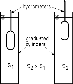
A hydrometer uses buoyancy to measure the specific weight of liquids. As will be discussed at the end of Chapter 3 in the lectures, the buoyant force on any object surrounded by a fluid or floating on a liquid is equal to the weight of the fluid that is displaced by the object. A hydrometer consists of a weighted bulb with a long, thin stem on top of the bulb (Fig. 1.1). The hydrometer floats in liquids with densities within the measurement range of the hydrometer. For a floating object of any kind, equilibrium of forces requires that the buoyant force be equal to the weight of the object. Consider a hydrometer floating in two liquids with specific gravities of S1 and S2 where S2 > S1. For the less dense liquid, the hydrometer must sink lower into the liquid to obtain a buoyant force to balance the weight. For a more dense liquid, the hydrometer does not sink as far into the liquid.
In the experiment, two hydrometers will be placed in graduated cylinders with water containing different concentrations of salt and therefore having different densities. The specific gravity of the fluid is read where the liquid surface intersects the stem of the hydrometer.
Fig. 1.1 - Apparatus for demonstrating measurement of S using hydrometers
Objectives:
1.2) Viscosity (Viscosity will be discussed in a later lab this semester.)
The dynamic viscosity (m) for a fluid [FT/L2]
is the ratio of the shear stress (t) acting on a fluid to the
resulting rate of angular strain, which is the velocity (V or u) gradient (dV/dy or du/dy)
where y is the coordinate distance normal to the direction of flow. For Newtonian fluids,
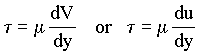 |
(1.1) |
In Chapter 2 of the text book, the velocity distribution for Poiseuille flow between
horizontal parallel plates was given as
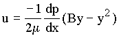 |
(1.2) |
where B = distance between the plates and dp/dx is the gradient of pressure in the flow
direction for horizontal flow and is negative since the pressure decreases in the flow
direction for horizontal flow. In one of the examples in class, the velocity distribution
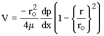
inside the tube was given as
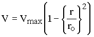 |
(1.3) |
for Poiseuille flow in a circular tube where ro is the radius of the tube.
Poiseuille flow in a tube exists when
 |
(1.4) |
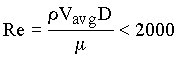
where Re is a dimensionless number called a Reynolds number, Vavg = average
velocity of flow in the tube, and D = tube diameter. Poiseuille flow is one type of flow
called laminar flow. In Chapter 10 of the text book, it is shown that Eq. 1.3
can also be written for horizontal flow as
 |
(1.5) |
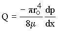
Integrating the velocity over the cross sectional area of the tube gives the volumetric
flow rate (Q) [L3/T] as
 |
(1.6) |
For a given pressure gradient, note that the volumetric flow rate is proportional to ro to the fourth power and inversely proportional to m.
In the experiment, there are three containers (Fig. 1.2) with 82 in. of approximately
horizontal tubing. The tubes for A and B are 1/4 in. copper tubing, which has an inside
diameter of 0.202 in. The third tube for C has an inside diameter of 0.054 in. A and C
have water while B has a mixture of water and glycerin to increase the viscosity. Each
container will be filled with liquid and allowed to drain through the tube. The pressure
at the downstream end of the tube is atmospheric pressure (zero gage pressure) for all
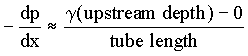
tubes. The pressure at the upstream end depends on the depth of liquid in the bucket above
the tube inlet. Thus, for each tube, the pressure gradient is given approximately by
 |
(1.7) |
Thus, as each bucket drains, the magnitude of -dp/dx decreases for the flow in the tube.
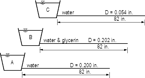
Fig. 1.2 - Apparatus for demonstrating effects of viscosity and tube size
Objectives:
 |
(1.8) |
where the coordinate system is as shown in Fig. 1.3, g is the acceleration of gravity, and t is time measured from the beginning of the trajectory. How can these equations for the trajectory be used to estimate Vavg for the tube?
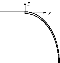
Fig. 1.3 - Jet trajectory and coordinate system
1.3) Vapor pressure
Vapor pressure (pv) is the partial pressure of liquid vapor, for example, water vapor in the atmosphere. Saturated vapor pressure (pvs) is vapor pressure that is in equilibrium with an open liquid surface at a given temperature and total pressure. Values of saturated vapor pressure for water are given in Table 1.1 and Fig. 1.4. This equilibrium is a dynamic one with the liquid vaporizing and condensing at the same rate at an exposed surface. Relative humidity is the ratio of the existing vapor pressure to saturated vapor pressure.
When the pressure to which a liquid is exposed is equal to the saturated vapor pressure for the temperature of the liquid, vapor pockets are formed continuously in the liquid. When the two pressures become equal due to an increase in temperature, the process is normally called boiling. When the two pressures become equal because of a decrease in the pressure associated with liquid flow, the process is called cavitation.
Table 1.1 - Saturated vapor pressure for water
| T | oC | 0 | 5 | 10 | 15 | 20 | 25 | 30 | 35 | 40 | 50 | 60 | 70 | 80 | 90 | 100 |
| pvs | kPa, abs | 0.61 | 0.87 | 1.23 | 1.70 | 2.34 | 3.17 | 4.25 | 5.63 | 7.38 | 12.30 | 20.00 | 31.20 | 47.40 | 70.10 | 101.30 |
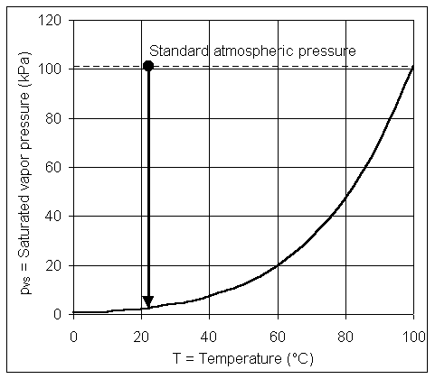
Fig. 1.4 - Saturated vapor pressure for water
In the experiment, a vacuum pump is connected to a closed bottle containing water. Before the pump is started, the temperature and pressure in the bottle are approximately as shown by the dot in Fig. 1.4. As the pump runs, the pressure in the bottle is decreased until it reaches the saturated vapor pressure. At that point, the water appears to be boiling, just as if it were on a stove.
Another part of the lab is to learn about mercury barometers. Barometers are devices for measuring atmospheric pressure. First, it needs to be recognized that vertical columns of fluids of height Dz cause a pressure change equal to gDz. Thus, pressures are sometimes expressed in terms of the height of the column of fluid rather than in traditional pressure units. It may be said that the standard atmospheric pressure is 101.3 kPa(abs), 14.7 psia, 760 mm of mercury, 29.9 in. of mercury, or 33.9 ft of water; all of these forms are equivalent.
A mercury barometer is made by filling an upright, open tube about 850 mm to 900 mm
long with mercury and then inverting the tube in a open container of mercury (Fig. 1.5).
The open container has atmospheric pressure acting on it. Inside the closed tube of
mercury, the pressure decreases with increasing elevation, so the pressures inside the
tube are below atmospheric. Since actual atmospheric pressure normally varies in the range
of (say) 740 mm of mercury (sometimes written as 740 mm Hg) to 780 mm Hg, the pressure in
the top part of the tube will drop to the saturated vapor pressure of mercury (Fig. 1.6)
and the top of the tube will have mercury vapor in it. Recalling that the height of a
column of fluid corresponds to a change in pressure, the height of the column of
mercury gives the difference between pvs for mercury and
atmospheric pressure. Mercury is used for barometers for two reasons:
(1) The specific weight is large enough that atmospheric pressure corresponds to a height,
which is relatively small (approximately 30 in. of mercury versus approximately 34 ft of
water).
(2) The vapor pressure of mercury for normal temperatures is approximately 106
times smaller than atmospheric pressure (Fig. 1.6) and thus can be considered to be
essentially absolute zero.
Since the scale on a mercury barometer is fixed on the side of the barometer and since atmospheric pressure corresponds to the height of the mercury above the free surface of the mercury, the free surface must always be in the same place when a reading is taken. There is a reference pointer in the open mercury container and also a plunger, which can be used to move the free surface to the location of the bottom of the pointer before a reading is taken.
Objectives:
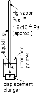
Fig. 1.5 - Schematic diagram of mercury barometer
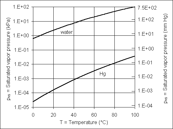
Fig. 1.6 - Saturated vapor pressure for water and mercury
In a liquid away from the liquid surface, the molecules have random orientations and cause an attraction on each other that is equal in all directions. However, the molecules are rearranged when a liquid surface is formed. The resulting unbalanced attraction of the molecules on each other causes the liquid surface to behave as if the surface were a stretched membrane. The tension in this hypothetical membrane, expressed as a force per unit length [F/L] and given the symbol s, is the surface tension of the liquid. The magnitude of the surface tension depends on the temperature and the second fluid (gas or liquid) in contact with the surface. Thus, the surface tension for water is different when the water is in contact with air and when it is in contact with an oil.
Although surface tension is present in a flat liquid surface, its effects normally cannot be seen. The effects of surface tension are most readily apparent in curved liquid surfaces, and the effects of surface tension increase as the radius of curvature of the surface decreases. It is surface tension that causes a water drop to form a bead on a table or that keeps a water drop in tact as it runs down a window pane. When a liquid surface is in contact with a solid surface, the angle of contact (q) between the liquid surface and the solid surface is an important parameter.
In the demonstration, open tubes with small internal diameters (d) are in colored
water. Surface tension pulls the water upward and into the tubes. The height (Dh) at which the water stands in the tubes is given by
 |
(1.9) |
Notice that the water is also drawn up a little way on the outside of the tube.
In another demonstration, a metal pin lies on a water surface. Since g for the metal is larger than g for water, the pin would sink if there were not a force to hold it at the water surface. The force comes from surface tension, similar to the force allowing the bug to stand on a water surface as in homework problem 2.37. As illustrated by Fig. 1.7, the vertical components of the surface tension forces (Fs) must balance the weight of the pin. (Notice that the magnetic field of the earth causes the pin to always point to the north. If it is manually rotated away from the north, it will rotate back to point to the north.)
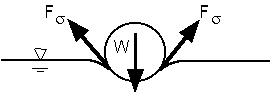
Fig. 1.7 - Forces on pin held by surface tension
Objectives:
The objectives are